It all began when the start battery died late last fall. Actually, that’s not entirely true. We knew the electrical system was incorrectly wired but were hoping to delay this project until our planned major pre-cruising refit once I retired in a few years. Yet I couldn’t bring myself to buy a new battery, even a cheap flooded lead acid starting battery, and wire it into a system that I knew was slowly trying to kill it. Thus a project began.
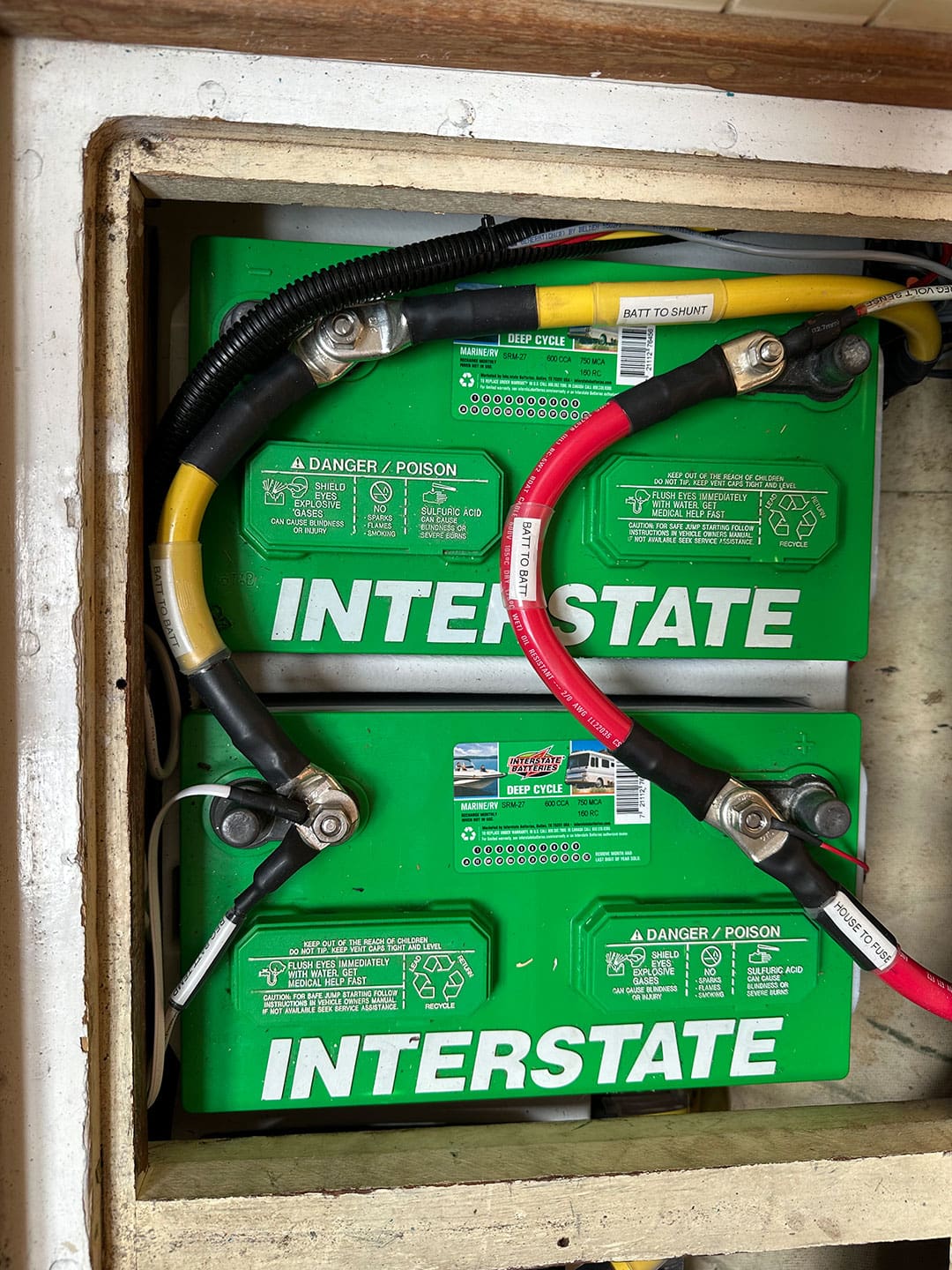
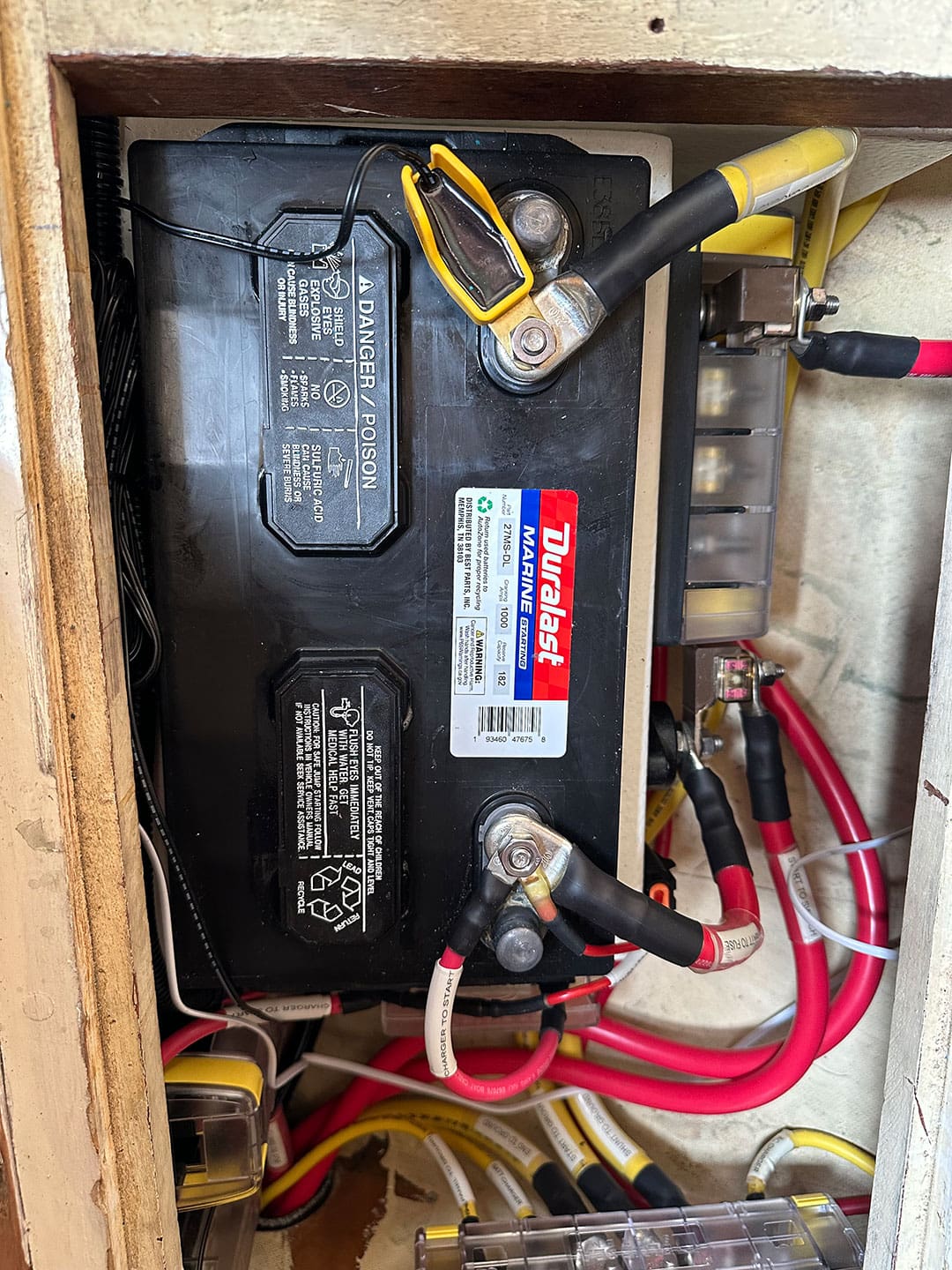
Our 28-foot 1986 Bristol Channel Cutter has minimal electrical demands compared to most contemporary cruising boats. She has navigation and interior lights, a propane detector and solenoid, a single cabin fan, VHF radio, chart plotter, and a couple of USB outlets. No refrigeration, no pressurized water, no electric bilge pump, and no on-board alternating current (AC) system; the AC battery charger plugs directly into shore power. Given these modest demands, and due to the limited room available, our electrical system was relatively simple. We had (and still have) two deep cycle Group 27 flooded lead acid batteries for house loads and one Group 27 starting battery for our Yanmar 3GM30F. As with many boats, the stock internally regulated Hitachi 55-ampere alternator was wired through a 1-2-Both switch and a diode battery isolator. The battery negatives were wired together and, along with the negative from the breaker panel, were connected to the engine block. There were no bus bars, fuses, or even any heat shrink on the cable terminations. While it’s clear that our system wasn’t even close to meeting American Boat and Yacht Council (ABYC) standards, what was killing our start battery is that both the house and start banks were wired to the same post on the battery isolator. When I found this, I moved the wires to the correct posts of the isolator. However, upon testing, I found there was no electricity flowing through this post. Apparently, some previous owner’s solution to the failed isolator was to wire both banks to the same post rather than replace the isolator! That meant the start battery was electrically connected to the house bank, regardless of where our 1-2-Both switch was placed.
The goal
Even with our simple electrical system, after thinking through this project we realized we needed to boundary the problem to avoid this becoming a year-long project. This led to two major decisions. First, we would stop the work at the distribution panel. In other words, we would install a new system from the house bank to the 12-volt distribution panel but would not replace the distribution panel itself or any of the wiring or components from the panel to the individual loads; that would be a project for another time. Second, we only wanted to do this once, so we would design and build in the potential for future growth and flexibility. This meant designing a system that could accept different battery chemistries, additional charging sources such as solar panels, and be ready for additional loads, like an inverter.
Preparation
While I do have an engineering background, it’s in mechanical engineering – not electrical. Since I have a hard time trusting anything I can’t physically see or touch, I was very reluctant to start this project. Fortunately, one of our dock mates is a retired U.S. Navy Master Chief Electronics Technician who was kind enough to act as a sounding board throughout this project. Having a mentor to bounce ideas off and from whom I could get a ‘gut check’ made me much more comfortable. Our efforts were also limited to 12-volt direct current (DC); no AC. I realized that if I took my time and use the resources available, then it was really just a mechanical project where we flip a switch at the end.
I prefer to research information from multiple reputable sources and use it to form my own opinions. I was already intimately familiar with Nigel Calder’s Boatowner’s Mechanical and Electrical Manual, which I then combed through with an eye towards the specific details we might need for this project. I had also previously taken a two-day in-person electrical course with Nigel through Cruiser’s University. Additionally, I spent a lot of time on marinehowto.com which contains a wide-range of extremely helpful articles by Rod “RC” Collins. There is also a Boat Electrical Systems Facebook group which is closely moderated and hosts a range of marine professionals. Through this Facebook group we sought, and received, some very helpful advice on a few detailed questions throughout this project. We even found a local ABYC master technician who was kind enough to crimp on some ferrules with professional grade tools, preventing us from buying a tool we likely wouldn’t ever use again.
The last resource I used extensively was boathowto.com (not to be confused with marinehowto.com). BoatHowTo is a collaboration between Jan Athenstädt and Nigel Calder with online courses on boat electrical and mechanical systems. Taking this course before beginning the project was one of my best decisions.
The course started at a very basic level and assumed little understanding of electrical systems, then built to a more advanced level that was presented in several different ways (videos, graphs, etc.) that proved useful when I needed to go back during the project to reference information.
Jan and Nigel were also very responsive to questions posted in the course. This helped as we were fine tuning the design.
Perhaps most useful, the course included a tutorial on EasyEDA, online design software for electrical schematics similar to AutoCAD. I’m a pencil and paper kind of guy, so it never occurred to me to use a computer-based design tool. However, the software, coupled with BoatHowTo’s tutorial and custom icons that included fuse blocks, bus bars, and other useful items, saved me countless hours as we iterated through multiple designs. This approach enabled us to produce a professional-looking wiring diagram that will serve us well for future reference and modification.
Design
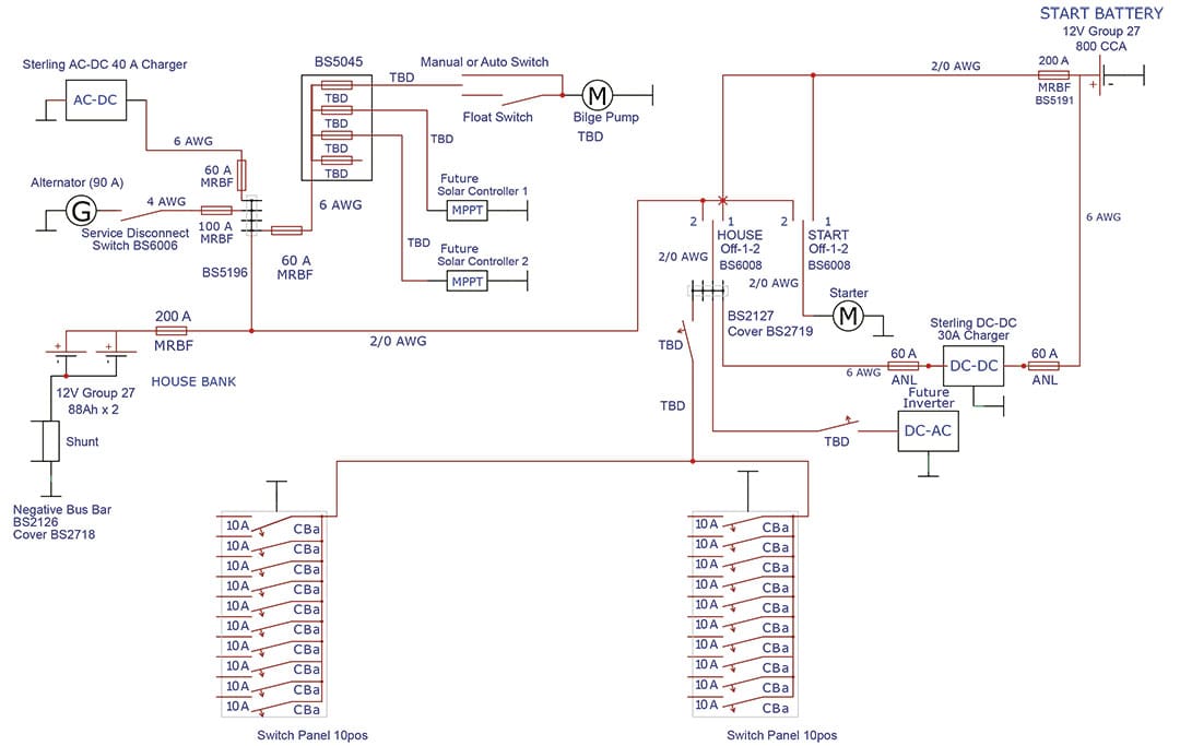
As mentioned earlier, in addition to ensuring the new system met or exceeded ABYC standards, we also wanted flexibility for different battery chemistries, including lithium ion, and future electrical system growth. This led to several key design elements. For example, we installed bus bars with extra physical capacity and selected conductors using potential future current draws for amp capacity and current drop calculations.
We designed the system to have all charging sources charge the house bank and used a battery-to-battery charger to charge the start battery from the house bank. This ensures both banks can be charged using their design charging profiles independently, and focuses the higher capacity charging sources (i.e. AC charger and alternator) on the presumably more deeply discharged house bank. We chose a Sterling battery-to-battery charger to charge the start battery. We previously replaced our original ferro-resonant AC charger with a Sterling charger and have been very happy with it. Our choice of Sterling for both the AC charger and battery-to-battery chargers was based heavily on several articles on marinehowto.com.
We were very close to choosing Victron for both given their reputation and wide range of adjustment parameters. However, the Victron models appropriate for our system could only be controlled via Bluetooth or a separate networking display. I didn’t want to have to pull out my cell phone in the middle of the ocean to control our electrical system, and we didn’t want to install a complex monitoring and control system. While a networked system may be more elegant, and perhaps even more efficient, it struck me as unnecessarily complex and perhaps even result in a single point of failure. The only downside I’ve found to the Sterling equipment is that the instructions are not very clear and the controls are a bit clunky. However, they have the ability to modify all aspects of the charging profile, and can be controlled and monitored from the chargers themselves. We did have an issue with the initial battery-to-battery charger not working correctly, but Sterling’s customer service was exceptional; they quickly got back to me with troubleshooting help and, when that didn’t work, immediately initiated a warranty claim to get us a new charger. In hindsight, choosing a battery-to-battery charger with so many variable parameters is likely overkill just to keep our start battery charged, but it provides future flexibility and wasn’t more complex or expensive than other less adaptable chargers.
We also decided to install an upgraded, externally regulated alternator as part of this project. We were initially leaning towards one of Balmar’s 6-series alternators but eventually decided not to for several reasons. Given the layout of our boat, without significant modification, the absolute largest house bank we could reasonably install would be 300-ampere hours. Even if this was a lithium system and it was deeply discharged, a high output alternator would likely only be operating near maximum load for an hour or two. Further, our little 30 horsepower Yanmar would only be able to handle a moderately sized alternator; assuming some inefficiencies, a 100-ampere alternator uses about five horsepower. Research also indicated that anything larger than a 100-ampere alternator should include a serpentine belt to limit slip or excessive bearing loads. That would require installing new pulleys, and likely require mounting modifications to ensure proper alignment.
In the end, I purchased a Hitachi 90-ampere alternator, which is the same model Yanmar uses on their larger four-cylinder engines, and had it modified by a local alternator shop for external regulation. This meant the installation of the alternator became plug and play, at least from a mounting perspective. The Hitachi is probably not as robust as the Balmar, although neither is constant-duty rated, but we used the external regulator to derate it slightly to ensure no belt slip and limit heat output to increase its life. So far, with our two Group 27 flooded lead acid house batteries and our modest electrical loads, we have only seen it near maximum output for about 20 minutes, and that was after purposely deeply discharging the batteries to test the charging system.
One of the disadvantages of the Hitachi alternator, which I did not consider until we were conducting the installation, is the output post is relatively small, notably smaller than on Balmar alternators. In fact, we were unable to find 1/0 lugs that properly fit the post. The largest size cable lugs available to fit the Hitachi was four gauge, which still met the maximum ampacity requirements, but results in a voltage drop of approximately 6% at the alternator’s full 90-ampere output. However, in addition to derating the alternator as described above, we ensured the voltage regulator was wired to sense voltage at the battery bank directly, so the voltage drop should not affect charging performance. Regardless, this smaller post likely results in a point of higher electrical resistance and therefore additional heat generation. While I believe this is acceptable for our installation, it’s certainly not ideal and worth considering when designing your electrical charging system.
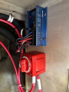
Research on external voltage regulators steered us towards Balmar. Wakespeed had more capability and features, although at a price point to match. I was thinking the Wakespeed might be worth the money when fate intervened. While walking the tables at a boater’s yard sale, I stumbled upon a new-in-the-box Balmar 614 for $5. As I started asking the seller if he really only wanted $5 and to confirm it worked, my wife, who is much smarter than I will ever be, immediately handed the man $5 and dragged me away before he could change his mind.
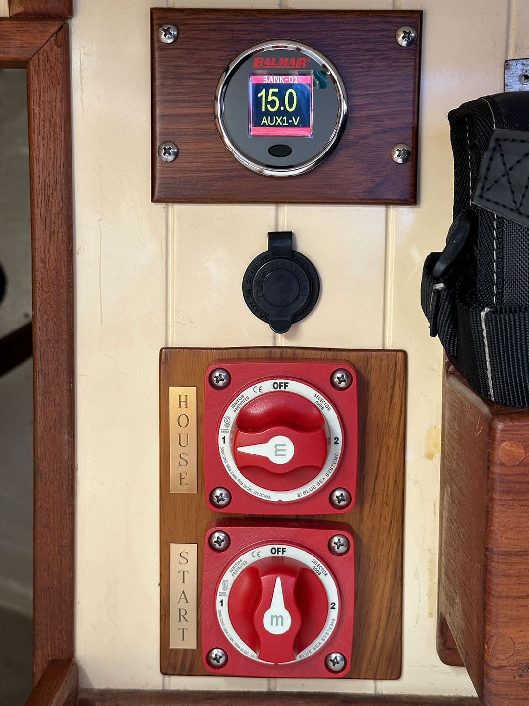
After extensive research on different battery monitors, I had narrowed down the range of options to a Victron 700-series, Balmar SG-200, or one of Blue Sea’s panel mounted monitors. Given this technology is continually evolving and our current electrical needs were relatively modest, we finally decided to forego any battery monitor during this initial refit and rely solely on the voltage meters currently installed on the distribution panel. I recognized this was not an ideal method to measure remaining battery capacity, but given that we currently intended on using flood lead acid batteries for both the start and house banks, it seemed a reasonable short-term solution. However, fate intervened again and at the following year’s boater yard sale, we stumbled across a new-in-the-box Balmar SG-200 for $50. While I’m uncertain how accurate the state of charge and state of health measurements are, the voltage and net current flow measurements are very accurate when compared with a multimeter. I also underestimated how useful the net current flow has been to monitoring the electrical system and we are glad we decided to install a battery monitor.
When designing the system, we spent quite a bit of time trying to figure out the best way to include the ability for the house bank to start the engine in the event the start battery died. In many installations, including our original configuration, the 1-2-Both switch is used to parallel battery banks for redundancy. However, using a 1-2-Both switch has several disadvantages including placing batteries with different chemistries, or at least charging profiles, in parallel and often noted concerns about forgetting the switch in the wrong setting. As such, our new system has two Off-1-2 switches. One switch controls the house circuit and the other controls the starting circuit. The ‘1’ position connects the house battery bank and the ‘2’ position connects the start battery bank. In this design, either battery bank can power either the house circuit or start circuit, or both circuits together. But the two battery banks can’t be placed in parallel. These switches only control which batteries provide power to each circuit; they do not affect charging. As mentioned earlier, all main charging sources always charge the house bank, and the battery-to-battery charger always charges the start bank.
Designing the system to accomplish our goals and ensure it met ABYC requirements took a lot of research. Several times when I thought I was done, I would think of something else resulting in a modification to the design. Once I was done, or thought I was, being able to bounce the design off my mentor provided peace of mind that we weren’t missing anything. The second part of the design was component selection. While I described some of the key components above, I didn’t realize the challenge associated with methodically selecting all of the required items, such as bus bars, fuse holders, switches, etc. This required considering their function and limitations as well as physical constraints, which led to a lot of measuring, several mock-ups, and even returning some initial purchases and selecting alternatives.
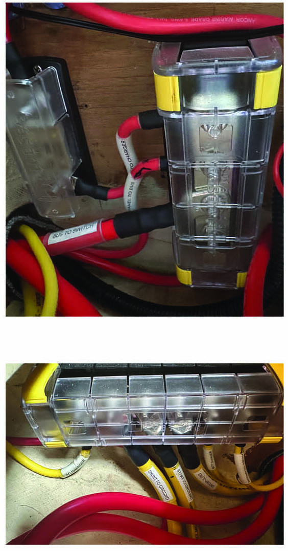
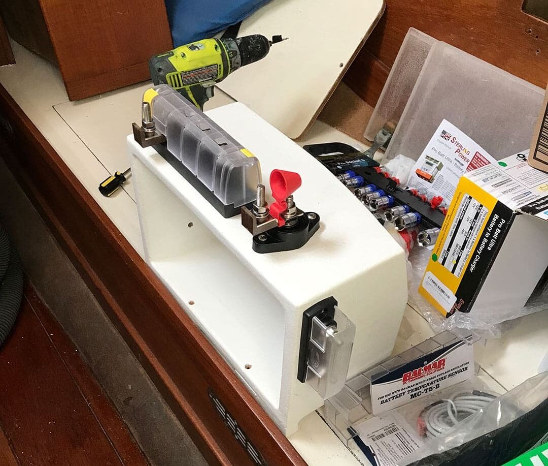
For example, due to space limitations, we could only use marine rated battery fuses (MRBFs) for the batteries. However, because of their height, we couldn’t mount the standard MRBF fuse holders directly on the battery terminals. We mounted the house bank fuse using Blue Sea’s MRBF surface mount fuse block (#5196) and the start bank MRBF on the side of the battery box using a Blue Sea’s PowerPost (#2002). As a side note, even though ABYC standards do not require fusing the starting battery, doing so seemed prudent, especially considering our system would permit the start bank to feed the house circuit. We added the major component part numbers and cable sizes to the wiring diagram. This helped tremendously when placing orders and then again when installing the system.
Installation and lessons learned
The physical installation took a lot less time than the research and design; in total it took the two of us about four weekends of work, not including rebuilding the battery boxes and modifying the bulkhead for the battery switches. The installation wasn’t difficult, but it was tedious and required us to maintain focus to ensure we measured carefully and made good crimps to avoid re-work and wasting cable.
After carefully estimating the length of different cable required, we found it was significantly more cost effective to buy cable by the full spool and we found genuine Ancor cable via Amazon for good prices. We initially planned to use Ancor lugs and a borrowed hydraulic dieless indent crimping tool. After reading several MarineHowTo articles, I was worried any die crimper would not correctly match the lugs and thought the dieless indent tool would provide better crimps than mismatched dies. In the end, it seemed penny wise and pound foolish after all the time, effort, and money we’d already invested in this project, so we bought the FTZ crimper recommended by RC Collins. This proved to be a great choice, making good consistent crimps for all of our lugs. We also used the recommended FTZ Power Lugs, except in a few applications where they wouldn’t fit due to space constraints or geometry. We were able to find 45-degree canted starter lugs and side mount lugs through Grainger, which we used in several of these spots. As a note, several sizes of the FTZ Power Lugs do not appear to be regularly stocked by any retailer and took over a month to ship, so we recommend ordering these early.
In addition to using heat shrink, we coated the bare cable with Kopr-Shield, a conductive anti corrosive copper-based paste, before installing the lugs. Although it is messy to apply, we’ve used it extensively on marine electrical connections to help fill any potential gaps between cables and terminations as an additional defense against potential moisture ingress and corrosion. To assist in tracing and future trouble shooting, we labeled both ends of every cable.
Mounting the battery switches was a significant project on its own, and one I would likely do differently if doing it again. First, we had to fill the hole in the bulkhead from the old 1-2-Both switch, followed by drilling new holes for the two new, and smaller, switches. Next, due to the thickness of the bulkhead compared to the depth of the switches, and the very limited space available, I used a router to back-cut the bulkhead for about half an inch around the battery switch holes. This ensured the lugs would lay flush against the switch terminals to make complete and proper contact. Lastly, the installation required connecting the 1 posts and the 2 posts on each switch to each other. Due to space constraints and the lack of flexibility of the 2/0 cable, we had a custom busbar made for one of these connections. While it was simple to find blank copper busbars, it was challenging to find tin-plated busbars. We found Farmers’ Copper, which was very responsive and produced exactly what we needed in a few weeks based on a drawing.
Wiring between the engine, alternator, and regulator was a bit complicated. We wanted to be sure we positively identified and connected the correct wires, so I traced and labeled each of the wires in the Yanmar wiring harness. Next, we wanted redu ndancy in the event either the alternator or external regulator failed, so we had the original 55-ampere alternator rebuilt, keeping it rigged for internal regulation. We then re-terminated the appropriate wires on the wiring harness and both alternators using quick disconnects, allowing a swap without having to cut and re-terminate the wires. Most of the wiring for the regulator was straightforward and R.C. has some articles that supplement the Balmar manual. We’d heard that programming Balmar regulators using the magnetic reed switch could be awkward. However, R.C.’s articles coupled with thoroughly reading the Balmar manual several times made this remarkably simple. I believe Balmar also has options that enable their new regulators to be programmed via Bluetooth.
As with all boat projects, this took longer than expected, with more time and effort on the design and planning side of the project than we anticipated, although part of that was me dragging my feet due to self-doubt. In the end, we’re happy with how the refit turned out and that we completed this project ourselves rather than paying someone else. I don’t think many installers would have taken the time to design in some of the unique features of our system, or been as careful with the installation. Perhaps most important, we’re confident we know our electrical system inside and out, which should help us with future troubleshooting. n
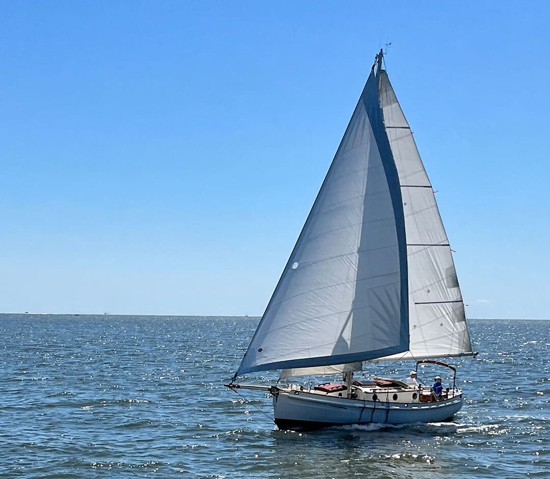
Michael Cilenti and his wife Beth enjoy working on Cymba, their 1986 Bristol Channel Cutter. Sometimes they even get to do some sailing on Chesapeake Bay, where she is currently berthed.