Nearly all marine engines are designed to be adjustable, to a point, relative to the propeller shaft by using adjustment or jacking nuts on their motor mounts. The adjustment should be thought of as no more than fine-tuning, the maximum range of vertical travel being limited to no more than an inch or two at the most, which is substantial when one considers that alignment is typically measured to just a few one-thousandths of an inch. Thus, the responsibility rests with the naval architect and boatbuilder to ensure that the design and execution of the engine installation guarantees near-perfect alignment with the shaft before the motor mounts are adjusted.
The other alignment
There is another side to the alignment story; it involves the support and position of the propeller shaft relative to its bearings, the shaft log (the tube through which the shaft passes) and the engine. While engine alignment is, or is expected to be, well understood by most marine industry professionals, shaft alignment is, on the other hand, far more esoteric and well understood by far fewer in the industry. In my experience, precious few truly understand its importance and the consequences of misalignment, and fewer still understand the techniques and processes involved in making adjustments and corrections.
Contrary to popular belief, shaft misalignment rarely leads to vibration, as the bow or offset induced in a shaft by misaligned bearings is constant. Improper shaft alignment can lead to excessive shaft drag and a resultant increase in fuel consumption, as well as accelerated bearing and shaft wear.
 |
|
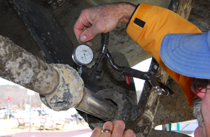
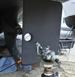
Shaft alignment can involve some esoteric measuring and alignment techniques. Make sure the boatyard crew working on your vessel is familiar with the process. |
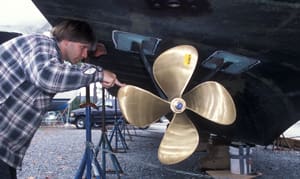
A few years ago, I inspected a vessel while it was hauled out. When I came to the propeller, I made an unsuccessful attempt to rotate it in order to gauge the condition of the bearings and alignment. Regardless of how hard I tried, I was unable to rotate either shaft on this twin-screw 60-foot vessel. This is a clear indication of either severe shaft misalignment (as opposed to engine misalignment, which rarely imparts this sort of resistance) or, less commonly, swollen shaft bearings. While final alignment of an engine to its shaft should only be carried out once a vessel has been afloat for 24 hours, even when hauled out the shaft should turn without undue effort once adhesion between it and its bearings is broken.
How shaft bearings work
In virtually all cases, propeller shafts are supported by one — and for longer shafts, sometimes as many as four — bearings, often referred to by their trade name, “cutless bearings.” Shaft bearings are pipe-like components, the outer shell of which is typically made of brass, or sometimes a fiberglass-like material (the latter is designed to be used on steel and aluminum vessels to avoid the corrosion potential caused by copper alloys), with an inner liner of grooved or fluted rubber. It comes as a surprise to many users that the sole source of lubrication and cooling is seawater; if water flow to the bearing is insufficient, or if it’s interrupted by marine growth or a line, net or other debris on the shaft, or if the shaft log water injection system is clogged, rapid bearing wear can ensue.
Shaft bearings may be found in and supported by struts — I- or V-shaped metal supports attached to the vessel’s hull, through which the shaft passes — and/or embedded within the shaft log in the keel or hull. When the vessel is built, the builder must make a concerted effort to ensure that bearings are properly located to support the shaft, while ensuring that they are also aligned with the theoretical shaft’s centerline, a line that is perpendicular with and begins at the center of the transmission output coupling, traveling aft through the bearings. The line must also be centered in and parallel with the bearings. If the builder is successful in ensuring this alignment, barring groundings or other damage, it should remain correct throughout the life of the vessel. While small adjustments may be made to the relationship between the engine and shaft by adjusting the location of the former, the shaft’s relationship to and alignment with the bearings should remain constant.
 |
|
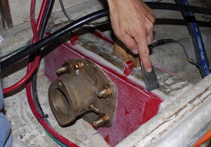
Using epoxy set the position of a block on which a shaft bearing has been mounted. |
Analysis and adjustment
In practice, it’s not uncommon to encounter shafts and bearings that are misaligned, and the greater the number of bearings, the greater the likelihood of misalignment. While shaft-to-bearing alignment can be challenging, aligning a shaft to several bearings, as well as the general location of the engine, can be daunting. As such, it’s easy to see how this process can go awry while the vessel is being built.
Traditionally, during construction or repairs, the process begins with a length of small-diameter yet stout string or wire, which is adhered to the center of the transmission output coupling. It is led aft through the shaft log toward the rudder, where it is anchored typically to a weighted object like a jack stand. Using this string or wire as a reference point, bearings (and, if present, struts) are positioned. When properly aligned, the bearings must remain centered on and parallel with the string or wire.
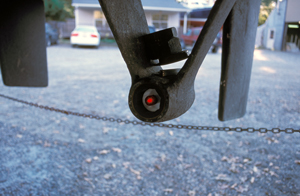
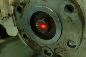
While this traditional approach is still used, more modern tools are now routinely employed; these include lasers and optical sights. Using a laser or sighting tool, an installer can position one or more bearings along the sight line with great accuracy. While this aspect of shaft alignment is critical, it’s the easy part. Setting the bearings in place permanently can be more challenging.
 |
|
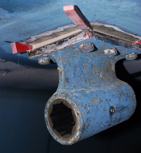
Wedges are used to adjust the height and orientation to the shaft centerline. |
Initially, the strut or bearing is “dry fit.” That is, it’s positioned roughly to determine what needs to be done to align it with the shaft. The process typically involves a technique known as “casting.” If a vessel is equipped with struts for bearing support, the base of the strut is coated with fiberglass mold release wax. It is then set into a mixture of thickened reinforced epoxy and positioned so that it remains centered on and parallel with the string, laser or optical sight or shaft line. The strut is “hung” from support fasteners, and wedges are used to adjust its height and orientation to the shaft centerline. Once the position is set, the epoxy is allowed to cure, after which — thanks to the wax — the strut is easily removed. Wax is removed from the strut and the epoxy surface, and the strut is then set in bedding compound, ensuring a watertight seal with the hull. In some cases, the bearing centerline may be below that of the shaft. In this instance, depending on the degree of misalignment involved, a recess may have to be made in the hull to accept the strut’s base, the strut may require modification or a new strut may need to be manufactured altogether.
A similar process is employed for bearings that reside within a shaft log and strut. The bearing itself is waxed and set in epoxy, and wedges are used to position it so that it remains parallel with and centered on the shaft line until the epoxy cures. All bearings should be a light press fit in the shaft log or strut. Ultimately, bearings are retained using set screws; a minimum of two must be used, and they should be installed at 60 degrees to each side of the bottom centerline, or at the 4 o’clock and 8 o’clock positions (alternately, they may be installed at the 3 and 9 o’clock positions, but not above the horizontal shaft centerline). Set screws must be harder than and galvanically noble to the bearing shell; indentations (not holes), which the set screws engage, should be drilled into the bearing shell using a drill bit with a tip angle that matches that of the set screw. A thread-locking compound should be used on set screw threads.
|
A high-tech method for setting up proper alignment is to use an alignment laser. Using a laser, an installer can position one or more bearings with great accuracy. |
  |
Ultimately, once the shaft-to-bearing alignment is complete, even a long and large-diameter shaft should — with the benefit of nothing more than light lubrication from soapy water — rotate with relative ease using one hand.
Before entrusting your vessel to anyone for shaft alignment analysis or adjustment, carefully scrutinize their knowledge and experience on this all too important yet frequently misunderstood subject. Don’t lead; simply ask, “How do you ensure the shaft is properly aligned to the bearings?”
Steve D’Antonio is an ABYC-certified master technician and owns Steve D’Antonio Marine Consulting.